

We've built a robotic surface. The mattress is not a single slab; it is 42 independently actuated blocks, each capable of 250 mm of vertical motion. When they move, the duvet moves with them. Or rather, it doesn't. It bunches. It slides. It leaves the bed partially uncovered at 3 AM revealing all those discrete blocks.
The instinct is to solve this with motors. Add a motorised retractor at the foot of the bed, wire it into the actuation controller, and synchronise duvet tension with block movement. We tried that. It worked technically. But it added weight, wiring, noise, and failure modes. More importantly, it violated a principle we hold: if a problem can be solved with physics alone, it should be.
The real question was simpler and harder: can a passive spring mechanism apply a constant pulling force across 600 mm of linear stroke, at a force low enough not to disturb sleep but high enough to keep a duvet in position through continuous mattress reconfiguration?
This article explains how we answered that question.
The Core Constraint
A conventional spiral torsion spring does not produce constant force. As it winds, its output torque increases. Translate that to a spool pulling a strap, and you get a force profile that climbs with extension. At full stroke, the duvet is pulled taut. At minimum stroke, it sags. Neither state is acceptable for a sleeping surface that adjusts itself throughout the night.
What we needed was a flat force curve: the same pulling force at 50 mm of extension as at 500 mm. The spring type that achieves this is called a constant-force spring — sometimes referred to as a power spring in industrial contexts. It is a strip of pre-stressed spring steel wound in a tightly coiled configuration. When the strip unwinds from the coil, the restoring torque remains nearly uniform across the full range of rotation. That uniformity is the entire point.
The target we set for ourselves was precise: deliver between 5 N and 15 N of linear pulling force with a preferred operating point of 10 N across a stroke of 500 to 700 mm. Silently. Passively. Inside a housing compact enough to fit within a bed frame.
The Force Window
The target range of 5 N to 15 N is not an assumption. It is the result of testing across multiple bedding fabrics — cotton, microfibre, linen, and weighted duvet covers — each with different surface textures, weights, and friction characteristics. A single theoretical friction coefficient cannot represent that range. The floor was set at 5 N because below it, no tested fabric reliably retracted. The duvet simply stayed where displacement left it.
The ceiling is set by the bed's own geometry, not by comfort. When a block rises 250 mm, the duvet must lift freely with it. A spring pulling too hard holds the fabric laterally taut against a rising block. The continuous layer cannot lift — it tents. Adjacent blocks lose contact with the surface and the mattress geometry is disrupted from above. That failure mode appeared consistently above 15 N across all tested configurations.
The preferred operating point of 10 N sits at the midpoint of this window. It clears the retraction floor with margin, stays below the tenting threshold with margin, and absorbs manufacturing tolerance and fabric variability without drifting into either failure mode.
The Governing Relationship
Every mechanical design has a governing equation. Ours is simple, which is exactly why it took time to get right.
T = F × R
Where T is the torque produced by the spring in N·mm, F is the linear pulling force applied to the duvet in Newtons, and R is the effective radius of the spool in mm.For our preferred operating point — a linear force of 10 N and a spool radius of 20 mm — the spring must deliver a constant torque of 200 N·mm throughout its entire operational rotation.
θ = L / R
The second relationship governs how much the spool must rotate to achieve a given stroke. For a 600 mm stroke and 20 mm radius, θ = 30 radians, or roughly 4.8 full turns. This is the rotational window across which the spring must maintain its torque output. If torque drops at any point in that range, the duvet slackens. If it spikes, the fabric bunches.
Selecting the Spring
Constant-force springs are not exotic components. They appear in seatbelt retractors, cable reels, and cord management devices. But those applications operate at force levels and stroke lengths that are entirely wrong for our use case. A seatbelt retractor delivers hundreds of newtons over a short throw. A cable reel delivers moderate force over moderate distance. Neither is designed for the specific window we occupy: low force, long stroke, zero noise, compact packaging.
We sourced cold-rolled spring steel strips with a width between 8 mm and 20 mm and a thickness between 0.1 mm and 0.5 mm. The strip is wound concentrically between the inner shaft and the interior wall of the cylindrical housing. The outer end of the spring is anchored via a tang — sometimes called a hook — to a fixed retaining slot on the housing wall. The inner end is fixed to the central shaft. When the shaft rotates in the rollout direction, the spring winds tighter, storing energy. When released, it delivers that stored energy as a constant reactive torque.
The critical design variable is torque flatness across the full rotational range. A spring that delivers 200 N·mm at turn one and 180 N·mm at turn four is not constant enough.
F = Ebt³ / (26.4R²)
Strip geometry was selected by inverting this relationship directly. With a target force of 10 N and cold-rolled spring steel at E = 200 GPa, the equation reduces to a constraint surface across three variables: width b, thickness t, and natural coil radius R. Thickness drives the output cubically — doubling t increases force eightfold — making it the most sensitive parameter. Width b scales linearly and is bounded by the packaging envelope. Iterating within those bounds, a strip thickness between 0.1 mm and 0.5 mm and width between 8 mm and 20 mm spans the full 5 N to 15 N force window.
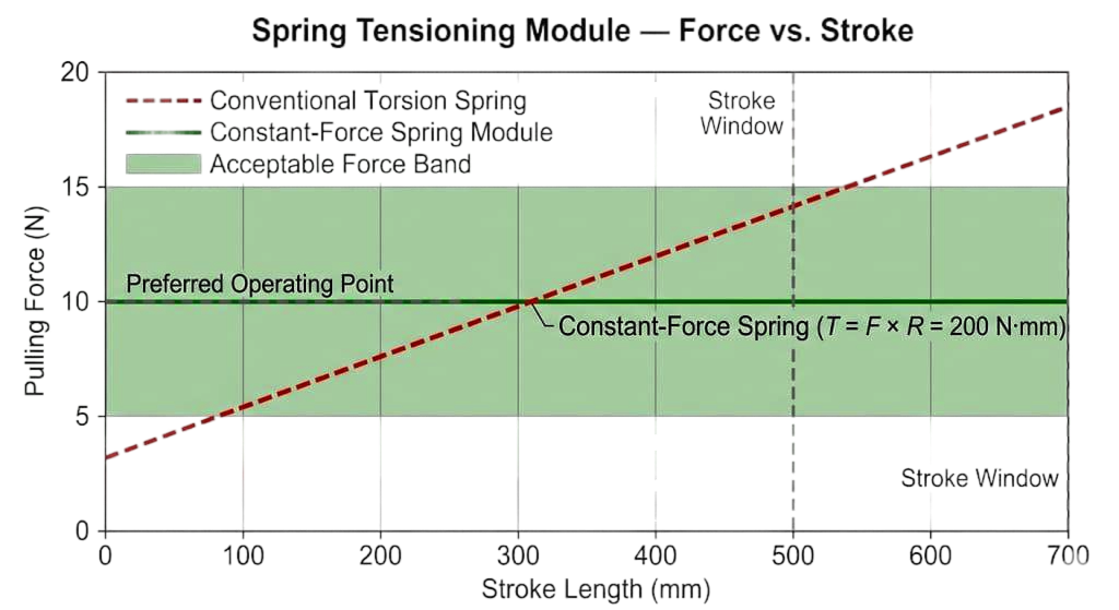
Fig. 1
Force vs. stroke graph. The constant-force spring module (green) holds at 10 N across the full stroke window, while a conventional torsion spring (red dashed) climbs continuously. The acceptable force band (5–15 N) is shown in green shading.
The Mechanism
The complete tensioning module comprises five elements: the spring housing, the inner shaft, the constant-force spring, the spool, and the flexible tension member.
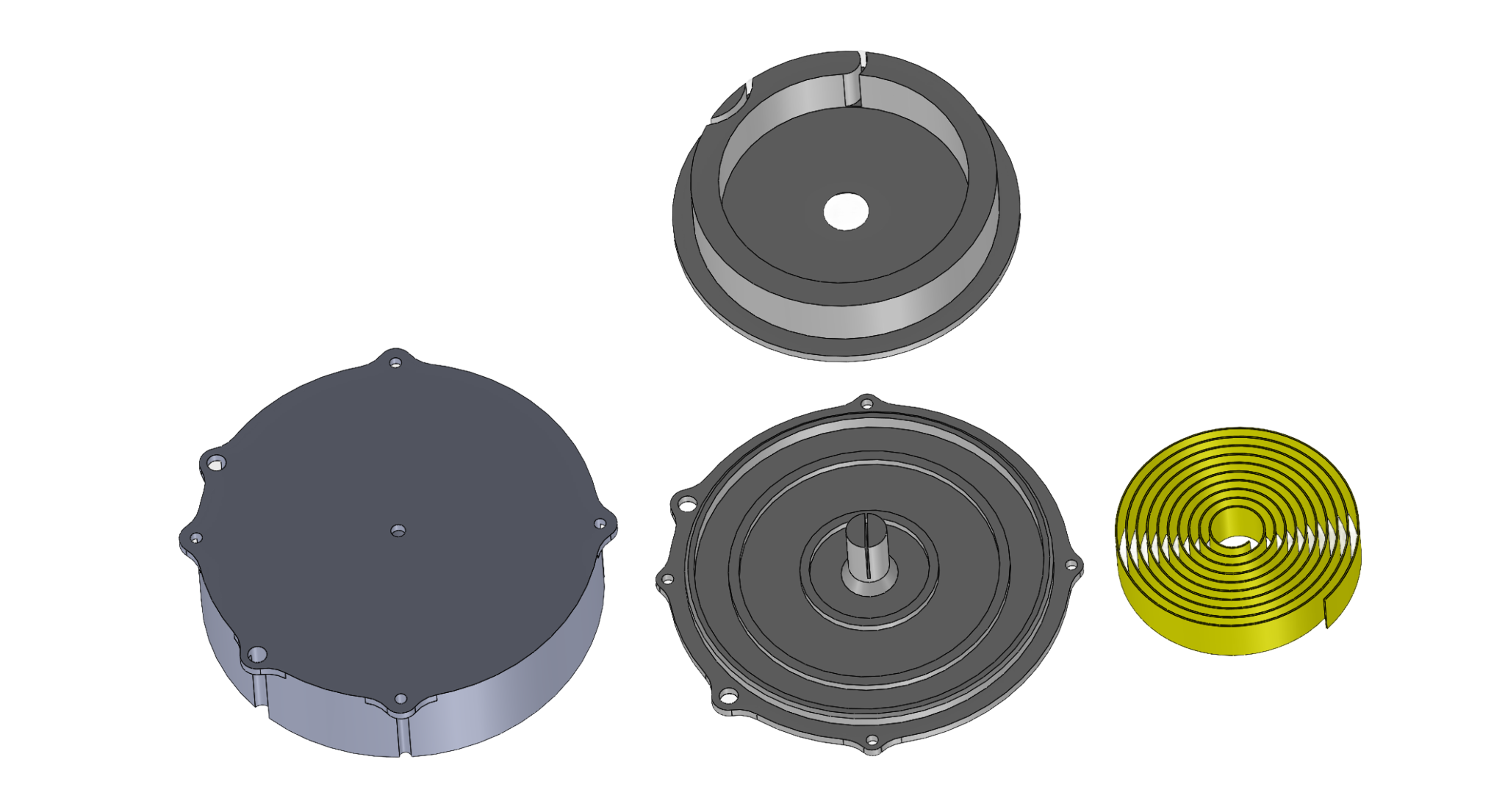
Fig. 2
Components of the spring housing. Clockwise from top: retaining ring, housing base with spool and central shaft, constant-force spring coil (yellow), and housing cover.
The spring housing is a cylindrical enclosure formed from either aluminium or 3D-printed PLA, fitted with a flanged mounting bracket for rigid attachment to the bed frame. It serves as the fixed reference point for the spring's outer tang and as the structural shell that protects the mechanism from dust, fabric interference, and mechanical contact with adjacent components.
The inner shaft sits at the centre of the housing, supported by low-friction bearings. It rotates freely under the reactive load of the spring. The spool is affixed to the shaft and co-rotates with it. Its effective radius — between 15 mm and 25 mm, depending on the force and stroke configuration — directly sets the mechanical advantage between the spring's torque and the linear pulling force. A 20 mm spool with a 200 N·mm spring gives 10 N. A 15 mm spool with the same spring gives roughly 13.3 N. The spool radius is the lever arm, and we chose it deliberately.
The flexible tension member — a textile strap, woven connector, or polymer-coated cable — is wound around the spool at one end and attached to the duvet at the other. As the mattress blocks actuate and the duvet displaces, the strap stretches out against the spring's torque. When the blocks retract, the spring retracts the strap, pulling the duvet back into position. No controller. No power supply. No signal processing.
Multi-Point Distribution
A single spring module at one edge of the bed would pull asymmetrically. The duvet would track correctly along one axis and drift along the other. The solution is distribution: we mount multiple modules along the bed frame's structural member, spaced symmetrically at intervals between 150 mm and 350 mm.
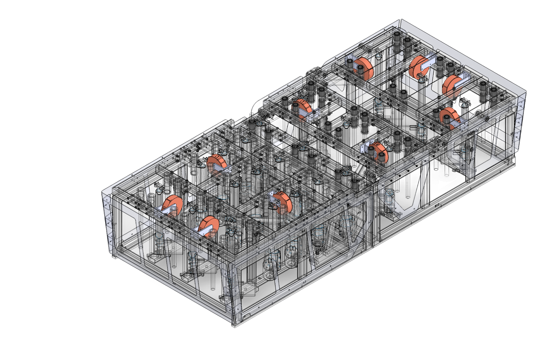
Fig. 3
Smart Bed Frame Internal Assembly (transparent/wireframe view). Multiple spring-driven tensioning modules (orange) distributed across the structural frame, alongside actuation and support components. Mattress surface removed for clarity.
Each module operates independently. There is no mechanical linkage between them. The duvet is attached to each spring module's tension member at discrete points along its edge. When a mattress block in the head zone rises, the modules nearest that zone respond. When a block in the leg zone drops, the corresponding modules compensate. The result is a spatially distributed, passively coordinated tensioning response that tracks the bed's geometry in real time.
This multi-point architecture is what makes the system work for a robotic bed specifically. A conventional adjustable bed has one or two moving sections. Ours has 42. The geometric complexity of duvet displacement in our system is an order of magnitude greater. A single retractor — no matter how well-tuned — cannot compensate for spatially non-uniform displacement across a surface with dozens of independent actuators. Distributed modules can.
The Design Window
We define the operational design window as the intersection of four constraints.
Force range: 5 N to 15 N. Below 5 N, the duvet sags due to friction. Above 15 N, the fabric tension becomes noticeable to the sleeper. Our preferred operating point is 10 N — firm enough to maintain coverage, gentle enough to be imperceptible.
Stroke length: 500 mm to 700 mm. This range covers the maximum displacement geometry of our 42-block platform at full articulation. The preferred stroke is 600 mm.
Torque flatness: The spring must deliver its rated torque — 200 N·mm at the preferred operating point — across the entire 30-radian rotation without significant decay or spike. This is the hardest constraint to meet in practice, because it depends on spring material properties, coil geometry, and manufacturing tolerances.
Packaging envelope: The module must fit inside a standard bed frame. Housing axial lengths between 60 mm and 120 mm. No protrusions beyond the frame's outer surface. This rules out large-diameter springs and mandates tight coil geometry.
What We Learned
The assumption embedded in most spring-retractor engineering is that these mechanisms belong in high-force, short-stroke, single-point industrial applications. Seatbelts. Cable reels. Extension cords. The underlying assumption is that distributing low-force, long-stroke spring modules across a piece of furniture would be mechanically redundant or impractical.
We found the opposite. The distributed architecture is what makes the constant-force characteristic useful. A single constant-force spring pulling from one point cannot compensate for the complex, spatially varying displacement pattern of a 42-block mattress surface. Multiple independently operating modules — each calibrated through the same governing relationship T = F × R — collectively maintain uniform coverage across the entire sleeping surface.
The spring does not know the bed is moving. It does not need to. It stores energy when the strap extends and releases energy when the strap retracts. The physics is the controller.
Closing Note
This work is part of a broader effort at Water Robotics to reduce the complexity of robotic sleep systems by solving mechanical problems with mechanical means wherever possible. The constant-force spring tensioning system described here is protected under provisional patent specification filed with the Indian Patent Office under The Patent Act, 1970.