

The question a mattress has to answer
CAMA is an adaptive sleep system that supports a sleeper's posture through the night. Before it can do any of that, it has to answer one question, continuously, for eight hours: where is the body on the bed right now? It needs to locate the head, shoulders, hips, knees, and heels in real time. No cameras, no wearables, no cooperation from the sleeper, no external reference.
Everything else in the product is downstream. The 42 actuated columns, the posture model, the nightly adjustments, the firmware. None of it works if the bed doesn't first know what's lying on top of it. The hard engineering problem in CAMA is not actuation. It's sensing. More specifically, it's sensing a soft body through a soft mattress.
The sensor placement dilemma
We sense the body with a full-bed pressure grid: a continuous piezoresistive film that changes resistance under load. Each column carries its own sensing zone, and the zones tile together into a bed-wide array. The cell pitch across the full grid is ~25 mm, giving a spatial Nyquist limit of ~50 mm. That's enough to resolve a shoulder from a hip, though not fine enough to pick out individual fingers. Anything the mattress blurs beyond 50 mm is gone for good. So the whole mattress design hinges on one choice that sounds small and is not: where inside the stack do we put the grid?
Near the top, close to the body, the readings are sharp. Every contour (shoulder, hip, heel) shows up as a crisp pressure feature. But that position destroys the product. Piezoresistive film at the surface wears out in weeks under nightly shear, and a sleeper can feel the film through the top layer. In a premium bed, both of those are disqualifying.
At the bottom, under everything, the sensor lasts indefinitely and the bed still feels like a bed. But by the time the body's pressure has traveled through every layer of foam and latex, the signal arriving at the grid is smeared, delayed, and attenuated. The shoulder and the hip no longer look like a shoulder and a hip. They look like two warm blobs.
That smudged signal is the real problem. It's not a sensor problem (the piezoresistive film itself is fine). It's a problem of what the mattress does to the signal on its way down. We ended up placing the sensor partway through the stack, above the structural layers (rebonded foam and ply) and below the comfort layers (super soft foam and latex). This gives us a sensor that's protected from body shear, mechanically supported by the rebonded beneath it, and reading a signal that has only passed through two foam layers and a silk sheet rather than the full mattress.
Why no single formula solves it
If every mattress behaved the same way, the smearing would be a fixed transformation and we could invert it once. Mattresses don't behave the same way. Memory foam softens at body temperature and delays pressure in time. Latex spreads it out in space with high fidelity but finite lateral coupling. Pocket coils scatter it through discrete, nonlinear spring paths that depend on where the coil happened to be touched. Each material has its own impulse response, and those responses change with temperature, load, and age.
A single fixed deconvolution formula can't recover posture across mattress types. The only way through is to fix the mattress. Build one stack whose blur kernel we understand well enough to invert, then build the model against that specific stack.
The three constraints, pulling against each other
Every decision in the mattress had to satisfy three constraints at once:
First, comfort. A premium continuous sleeping surface. Pressure variation below the Weber threshold at every body region, every posture. Weber's law for cutaneous pressure perception says the just-noticeable difference scales with baseline pressure:
ΔP / P = k, with k ≈ 0.05 (design target)
Published cutaneous pressure JNDs range from k ≈ 0.07 to 0.14 depending on body site and adaptation state (Gescheider, Bolanowski et al.). Our target of 0.05 sits below the lowest published threshold. That’s an aggressive choice, not a conservative one. The reasoning: sub-threshold at every zone simultaneously is harder than sub-threshold at any single zone. We assume the sleeper integrates discomfort across non-contiguous body regions, a hypothesis informed by within-region spatial summation studies, though cross-region summation is not well-established in the psychophysics literature. At ischial tuberosities (baseline ~6–10 kPa), k = 0.05 means a change of ~0.3–0.5 kPa. At the calves (~0.5–2 kPa), substantially smaller absolute changes. Every zone must stay below this line at the same time.
Second, a deconvolvable signal. Whatever pattern reaches the pressure grid (which sits partway down the stack, above the rebonded foam) must retain enough spatial information to recover body landmarks like head, shoulders, hips, knees, and heels to within a few centimeters.
Third, the discrete-column geometry. CAMA’s mattress is 42 independent vertical columns, each roughly 130 × 130 mm in footprint (6 columns wide by 7 long, tiling a standard mattress), each with its own actuator. Below the birch-ply cap, air gaps of ~5 mm separate columns. No stress transfers laterally. Every load on a column’s surface is carried by that column alone.
These constraints fight each other. Comfort wants soft, continuous, conformal. A clean signal wants stiff, local, non-dispersive, close to the body. Discrete columns force load concentration that neither of the first two can tolerate on its own. The mattress is the point where all three are simultaneously satisfied. No earlier version of it managed that.
The discrete columns, reread
On a conventional mattress, load spreads. A first-order approximation uses a ~45° spread cone through the foam; the effective bearing area grows with depth:
A_eff,cont ≈ π (r + d · tanθ)²
with r the surface contact radius, d the foam depth, θ the spread angle. For a seated person (r ≈ 160 mm) on 150 mm of foam, A_eff ≈ 0.30 m². This spreading is great for comfort and terrible for sensing: a shoulder at the surface arrives at the sensor as a low-contrast halo overlapping the torso signal.
On CAMA, spreading terminates at the ply under each column. There is nothing below the ply but air gaps and the adjacent column’s ply. Stress cannot jump air. Whatever load lands on a column goes straight down, so the effective bearing area below the ply collapses to the column footprint:
A_eff,col = W × L (fixed, independent of depth)
This hurts comfort. A 75 kg sleeper distributes ~735 N across 8–10 columns (~75–90 N each), but sitting on the edge concentrates the same 735 N on one or two columns, up to ~370 N on a single stack. That’s a 4–5× load swing on the same foam with no relief path. But it gives sensing the one thing it needs most: a bounded, column-local blur kernel. The support of the point spread function at the sensor is limited to a column footprint, not a growing cone. The same geometry that makes the load problem brutal makes the inverse problem tractable.
The mattress as the thing you deconvolve through
The pressure grid sits above the rebonded foam, so the only layers between the body and the sensor are silk, latex, and super soft foam. Borrowing from acoustics, those three layers form a cascade of filters, and the end-to-end transfer function is the product of their individual responses:
H(s) = T_silk(s) · T_latex(s) · T_soft(s)
Each T_i depends on effective dynamic impedance Z_i, layer thickness d_i, and loss factor η_i. Rebonded foam and ply sit below the sensor. They contribute to structural support and actuator coupling but don’t filter the pressure signal reaching the grid. This is a design heuristic, not a predictive simulation. The foams are nonlinear, viscoelastic, and temperature-dependent, so strict LTI assumptions hold only locally.
At the sensor plane (above the rebonded, below the super soft foam), the measured pressure field is the 2D convolution of the body-contact field with the combined impulse response of the three layers above. Under an LSI approximation (valid for small-signal excursions around a fixed operating point):
y(x, t) = (h_stack * p_body)(x, t) + n(x, t)
In the 2D Fourier domain the convolution becomes a product, Y(u,v,ω) = H_stack(u,v,ω) · P_body(u,v,ω) + N(u,v,ω), and the regularized Wiener inverse gives the estimator we actually use:
P̂(u,v) = [ H*(u,v) / ( |H(u,v)|² + λ(u,v) ) ] · Y(u,v)
with λ(u,v) ≈ S_nn / S_pp the noise-to-signal spectral ratio (Tikhonov-equivalent for flat priors). The inverse problem is well-posed only where |H(u,v)|² is not overwhelmed by λ. Every spatial frequency the stack attenuates below the noise floor is a frequency we cannot recover. The conditioning of the recovery is captured by the ratio of extreme singular values of the discretized H, κ(H) = σ_max/σ_min. Compositions with large κ amplify noise catastrophically.
We did not pick a mattress first and then try to deconvolve through it. We ran the loop the other way. We built prototype stacks, measured h_stack, trained landmark models against the resulting y, measured where the models failed, and changed the stack to make the next round of deconvolution easier. The mattress composition we ship is the one the inverse problem kept converging on, not the one that looked best on a comfort chart.
Measuring the mattress: the single-block experiment
To characterize a candidate composition we run a controlled probe. Objects of known geometry and weight (rigid blocks, cylinders, L-shaped forms, varying in size and mass) are placed on a single-column test rig with a 24×16 pressure grid array at ~10 mm pitch (240 × 160 mm sensing area, covering one column with margin). Beside the mattress, the same object sits on a bare reference array: same cell pitch, same electronics, same weight, same position relative to the sensor origin. The bare reading is the ground truth, what the sensor should see if the mattress added nothing. The reading through the mattress is the convolution of that ground truth with the stack’s point spread function, plus sensor noise.
We ran this across multiple mattress compositions and, critically, with the pressure grid placed at different depths within each stack: above the latex, between latex and soft foam, between soft foam and rebonded, and below the rebonded. Each combination of composition and sensor position produced a different PSF. The position that survived was above the rebonded. Far enough from the surface to be protected from shear, close enough to the body to read a signal that has only passed through super soft foam, latex, and silk.
The block is rigid and its footprint is known, so we’re not trying to discover what we placed on the bed. We’re trying to discover what the bed did to it. Formally, given bare-array ground truth p(x) and through-mattress reading y(x), we estimate h(x) by minimizing the reconstruction residual with a Tikhonov-regularized least-squares fit:
ĥ = argmin_h ‖ y − h * p ‖²₂ + μ ‖∇h‖²₂
which in the Fourier domain reduces to Ĥ(u,v) = Y(u,v) · P*(u,v) / ( |P(u,v)|² + μ ). The smoothness prior μ‖∇h‖² rejects the high-frequency noise that naive inversion would amplify wherever |P(u,v)| is small.
We run the block at nine positions across the grid and several loads. Let ĥ_i be the PSF estimated at position i. We report three stationarity metrics:
translation drift: max_i ‖ ĥ_i − h̄ ‖₂ / ‖h̄‖₂ load drift: ‖ ĥ(F₂) − ĥ(F₁) ‖₂ / ‖ĥ(F₁)‖₂ for F₂ = 2F₁ shape entropy: S(ĥ) = − Σ_k ĥ_k log ĥ_k (normalised PSF)
A composition that looks good at one spot and bad at another is not a good composition. It means the PSF is position-dependent, and the deconvolution model can’t assume that away.
Why stiffer is not better, and softer is not better
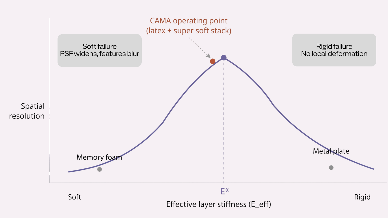
It’s tempting to conclude that the stiffest composition wins because lateral spreading is the enemy. It doesn’t. Consider a metal plate above the sensor. Apply a point force anywhere on its surface. Because the plate is rigid, it can’t deform locally. It can only translate or tilt as a whole. The force distributes itself nearly uniformly across the entire bearing area at the bottom. Every sensor cell beneath the plate reads roughly the same value regardless of where the load was applied. You’ve measured that a force exists, not where it was. Spatial resolution is zero.
The sensor’s ability to localize load depends on the layer above it being compliant enough to deform locally. When you push on one spot, that spot should compress more than the surrounding area, producing a pressure peak at the sensor directly below that falls off with distance. That local deformation is the signal. A stiff layer kills it.
Soft compositions fail the opposite way. The layer deforms too readily, load spreads laterally through the material, the PSF widens into a broad halo, and neighboring features merge into one warm region. Memory foam makes this worse in time as well as space. Its viscoelastic relaxation is well described by a Kelvin–Voigt element,
σ(t) = Eε(t) + η · dε/dt, retardation time τ = η/E
aand the non-dimensional Deborah number De = τ / t_process measures how far the foam lags the excitation. For tested memory foam grades, De ≈ 3–8 against a ~1 s actuator cycle. The material can’t reshape between frames, so the PSF carries history. H(u,v,ω) picks up a non-trivial phase in ω, and successive sensor frames are correlated in a way the LSI deconvolution ignores.
Plot spatial resolution (or equivalently, PSF sharpness, 1/FWHM) against effective layer stiffness and you get a curve that rises from the soft end, peaks at a particular stiffness E*, and falls again toward the rigid end. It’s not monotonic. It’s single-peaked. Below E*, the layer spreads load laterally (soft failure). Above E*, the layer refuses to deform locally (rigid failure). Every composition we tested lands somewhere on this curve. The experiment is a search for the peak, and the winner is the composition closest to it that also clears the comfort and noise constraints.
Three axes, one decision
A single number won’t rank compositions honestly, because the property we actually want is the joint of three things. We define each one quantitatively so compositions can be compared without hand-waving.
Distortion. Deviation of the recovered field from the bare-array ground truth. We score it jointly with three terms:
D = α₁ · FWHM(ĥ) + α₂ · S(ĥ) + α₃ · ( 1 − SSIM(p̂, p_gt) )
FWHM is the main-lobe full-width-at-half-maximum of the PSF, S(ĥ) is its Shannon entropy, SSIM is the structural-similarity index between the deconvolved reconstruction p̂ and ground truth p_gt. Lower is better. The weights were set by leave-one-composition-out cross-validation: for each candidate weight vector, we ranked the remaining compositions by D and measured rank correlation with the model’s landmark error on those compositions. The weights that maximized rank correlation were α₁ = 0.45, α₂ = 0.25, α₃ = 0.30. FWHM dominates because it directly predicts landmark localization error; entropy and SSIM serve as regularizers against pathological PSF shapes that FWHM alone misses. With only 14 compositions and 3 free weights, overfitting is a concern. We verified stability by checking that the rank ordering of compositions was unchanged across all 14 leave-one-out folds, and that perturbing any weight by ±20% relative didn’t change which compositions landed on the Pareto front.
Noise. Through-mattress SNR at the pressure grid, in dB:
SNR = 10 log₁₀ ( Σ_x y(x)² / Σ_x n̂(x)² )
with n̂(x) estimated from a no-load baseline frame. We also track the deconvolution noise gain, E[‖p̂ − p‖²₂] / E[‖n‖²₂], which is bounded above by κ(H)² for Tikhonov-regularized inverses. Compositions with ill-conditioned H blow this term up regardless of raw sensor SNR.
Comfort. Weber-fraction excursion across body regions under a body-shaped load fixture:
C = max_{zones z} ( ΔP_z / P_z ), target C < 0.05
These three trade against each other by construction. Pushing distortion down tends to raise stiffness and pull comfort down. Pushing SNR up favors thinner, denser foam and pulls comfort down. Pushing comfort up with softer or thicker layers widens FWHM(ĥ) and raises κ(H), pulling both of the other axes the wrong way. There is no global winner, only a Pareto front. A composition c is dominated iff there exists c′ with
D(c′) ≤ D(c), SNR(c′) ≥ SNR(c), C(c′) ≤ C(c), strict in at least one
Any dominated composition drops out. The selection happens over the remaining front.
The composition sweep
We tested fourteen compositions varying material (polyurethane, natural latex, memory foam), thickness in one-inch increments, and layer order. One candidate was a 4″ latex over 2″ memory foam stack, a plausible premium-mattress recipe included so the experiment had a known-comfortable baseline to beat on the other two axes. For each composition we recorded PSF width and entropy (averaged across nine block positions and three loads), SNR at the sensor at the same loads, and a comfort score from a short sleeper panel plus a body-shaped load-distribution fixture.
Each composition becomes one point in (distortion, noise, comfort) space. We plot the Pareto front and look at who’s on it. Compositions inside the front are dominated (some other composition is at least as good on all three axes) and drop out immediately. The interesting question is always which composition on the front to pick. For us that meant: of the points that satisfy comfort above our threshold, which has the narrowest, most stationary PSF?
The 4″ latex + 2″ memory foam baseline sat on the front for comfort but fell off it on distortion, for exactly the reason the single-block test was designed to expose. The memory foam layer turned the PSF into a time-varying smear. Removing memory foam from the sensing path and moving latex’s role to responsiveness rather than comfort is what led, after several more iterations, to the stack described below.
What the deconvolution experiments taught each layer to be
Rebonded foam (50 mm) sits below the pressure grid, between the sensor and the ply. It doesn’t appear in H(s). Pressure has already been measured by the time it reaches the rebonded. Its role is structural: it provides a stable, flat substrate for the pressure grid to rest on, damps actuator impulses traveling upward through the ply so they don’t corrupt the sensor reading from below, and bridges the stiffness discontinuity between the gigapascal-range ply and the kilopascal-range comfort foam. Rebonded foam’s support factor,
SF = ILD₆₅% / ILD₂₅% ≈ 2.8 (vs. 1.7–2.2 for uniform PU)
means it stiffens disproportionately under concentrated loads. That keeps the sensor plane mechanically stable even when a single column takes a 4–5× load swing. Without it, the pressure grid deformed into the air gap under edge-of-bed sitting, producing saturated, unreadable frames.
Super soft foam (ILD 8–12, 50 mm) sits directly above the pressure grid. It’s the first layer the pressure signal passes through. The constitutive behavior is Kelvin–Voigt with τ = η/E ≈ 0.8–1.2 s. Against a ~1 s actuator cycle, this gives De = τ/t_process ≈ 0.8–1.2, near unity, meaning the foam settles within roughly one cycle. Compare memory foam at De ≈ 3–8, where the surface can’t reshape between actuator events, so the sensor reads a blurred temporal average. Super soft foam is slow enough to conform into body hollows on initial contact and fast enough that each sensor frame is approximately independent. The hollows (lumbar, popliteal, cervical) are where landmark recovery matters most; pressure gradients at their edges otherwise read as spurious PSF features. 50 mm is the unique thickness that neither bottoms out at the 95th-percentile body load (which introduces a hard nonlinearity and breaks LSI) nor fails to fill shallow hollows for lighter sleepers.
Natural latex as the primary spring, above the soft foam. The hyperelastic response is well captured by a Mooney–Rivlin strain-energy density,
W = C₁ (I₁ − 3) + C₂ (I₂ − 3)
but the property that matters most here is hysteresis. The loss factor η (energy dissipated per cycle / energy stored) controls the temporal component of H(s):
| Material | Loss factor η | Energy return |
|---|---|---|
| Natural latex (Dunlop, ILD 28) | ~0.15 | ~85% |
| HR polyurethane | ~0.40 | ~60% |
| Memory foam (tested grade) | ~0.65 | ~35% |
In a comfort-only world, η is a feel parameter. In a deconvolution world, it’s temporal coupling. High-η materials carry residual strain across frames, so Y(ω) sees a low-pass smear of past P(ω) instead of the current field. Latex collapses the temporal component of h_stack to near a single frame (De ≪ 1 over the 0.01–2 Hz band of sleep movement).
Mulberry silk on top, continuous across all 42 columns. The first prototype used memory foam at the surface and we had to abandon it on three grounds. Thermal: measured bulk k ≈ 0.04 W/m·K, roughly half the conductivity of still air-adjacent textile systems and well below the ~0.10–0.15 W/m·K range of natural fibers, working against the ~1 °C core temperature drop sleep onset requires. Viscoelastic: Williams–Landel–Ferry shifts,
log a_T = − C₁ (T − T₀) / ( C₂ + (T − T₀) ) C₁ ≈ 14, C₂ ≈ 45 K, T₀ = T_g + 50 K ≈ −30 °C
drop modulus 3–5× between room and skin temperature, making H depend on ambient and skin conditions rather than design intent. And De ≈ 3–8 relative to a 1 s actuator cycle, so the surface can’t keep up with the mechanism. Silk solves all of this: k ≈ 0.15 W/m·K, hygroscopic, De ≈ 0, negligible VOC. It’s also the only layer continuous across all 42 columns, the single element that lets the sensor field be smoothed spatially without crossing a material discontinuity.
What did not survive
A 6-inch latex monolith was the natural simplification. One slab per column, do everything. Its axial resonance with an 80 kg load, estimated as f = (1/2π)√(k/m) with k = EA/t the axial spring constant of the layer, sits near 3.4 Hz. That’s inside the 2–5 Hz band of body sway during sleep-stage transitions, and actuator harmonics at 0.1–1 Hz excited it. The three-layer stack spreads the same energy across multiple damped modes with no dominant peak. The monolith also produced a wider, more load-dependent ĥ than the three-layer stack. The model consistently underperformed on it.
Memory foam in the comfort layer failed on Williams–Landel–Ferry shifts alone. A 3–5× modulus change between room and skin temperature is a variation the model can’t compensate without per-user thermal calibration. Combined with high hysteresis, it made h_stack non-stationary in time as well as in load.
Pocket coils, without lateral bracing from neighboring coils (which the discrete-column geometry forbids), buckled under repeated off-axis actuator loads within hundreds of cycles. Designs stiff enough to resist instability compromised compliance and packaging. They also produced a sparse, high-contrast sensor field that looked tractable in a single frame and was intractable in aggregate. Each coil’s contribution was spatially nonlinear and sensitive to contact location, violating LSI at the scale of the PSF.
HD polyurethane at the base, without rebonded, held its properties for six months and then compressed beyond 20% permanent set within a 2-year-equivalent accelerated-aging schedule. On a conventional mattress, sleepers drift across the surface and wear redistributes. On a column, the hip column takes the hip load every night and never gets relief. The rebonded’s mechanically interlocked structure stayed below 10% over the same period.
This raises a fair question: does the shipped stack’s PSF drift as the foam ages, and if so, is it recalibrated? The PSF is characterized at factory against the reference array and stored per unit. The bed runs a periodic self-check: during unoccupied hours, each actuator fires a known impulse sequence and the sensor reads the response. If the measured impulse response diverges from the factory baseline beyond a threshold (currently set at 10% relative FWHM shift), the firmware flags a recalibration event and updates the stored PSF. In accelerated-aging tests with latex and rebonded foam, this threshold was not triggered within the 2-year-equivalent period. For compositions that didn’t ship (HD-PU base, memory foam), it was triggered within 8–12 months equivalent. One more reason they were eliminated.
The complete stack
Top to bottom, per column (except where noted):
| Layer | Material | Scope | Primary function |
|---|---|---|---|
| 6 | Mulberry silk | Continuous | Thermal regulation, continuous surface across all 42 columns |
| 5 | Natural latex (4″ / 100 mm) | Per column | Primary spring; low-hysteresis signal path for deconvolution |
| 4 | Super soft foam (2″ / 50 mm) | Per column | Passive micro-conformance; first layer above sensor |
| S | Pressure grid | Continuous | Full-bed pressure sensing layer (~25 mm pitch) |
| 3 | Rebonded foam (2″ / 50 mm) | Per column | Sensor substrate; damps actuator transients; impedance transition |
| 2 | Birch ply (18 mm) | Per column | Rigid cap, column isolation, load distribution |
| 1 | Actuator | Per column | Active posture support |
The loop, stated plainly
A conventional mattress distributes load. CAMA routes it. Each column carries load down an independent path, cushioned above, sensed in the middle, structurally supported below. The pressure grid reads a field that has passed through only three layers (silk, latex, super soft foam), while the rebonded foam and ply beneath it provide the mechanical foundation and damp the actuator.
None of this was designed in sequence. Every change to the foam layout changed the pressure pattern at the sensor, which changed what the model could learn, which told us what to change about the foam. We placed the sensor at different depths, tested objects of different shapes across different compositions, measured PSFs, trained models, tracked where landmark recovery broke. The stack we ship is the fixed point of that loop. The one composition and sensor position we found where comfort, deconvolvable signal, and the discrete-column constraint hold at the same time.
The mattress is not the product. The product is a bed that knows where the body is, and a mechanism that uses that knowledge to hold the spine where it should be, breath by breath, all night. The mattress is the filter we chose because, of everything we tried, it was the one we could invert.